Blog · Structured light ·
Building a structured-light scanner out of a laptop and a phone
The hardware half of the scanner: why a projector and a camera have to sit where they sit, the crosshair trick that focuses both of them on the same point, and a browser rig (laptop as projector, phone as camera) that self-synchronises with no channel between the two devices at all.
- Interactive
- structured-light
- computer-vision
- gray-code
- camera
The last post in this series was all algorithm: how to label every row and column of a projector with a binary number, and why Gray code survives blur and noise at the boundaries where plain binary falls apart. None of that matters if the projector and the camera aren’t actually looking at the same patch of the world in a way the maths can use. This post is the part with clamps and gaffer tape in it (the rig), and then a browser version of it: your laptop screen as the projector, your phone as the camera, handing back a downloadable capture bundle that the decoder two posts from now reads directly.
The actual rig
Report §4.1 (p.7) lists what was on the table: a Panasonic PT-LB51 projector, a Canon 500D DSLR, a Microsoft Kinect for the Xbox 360 (scanned alongside the structured-light rig for comparison, with its own power adapter since the Xbox doesn’t supply enough over USB alone), and a laptop running the capture software that drives all three.
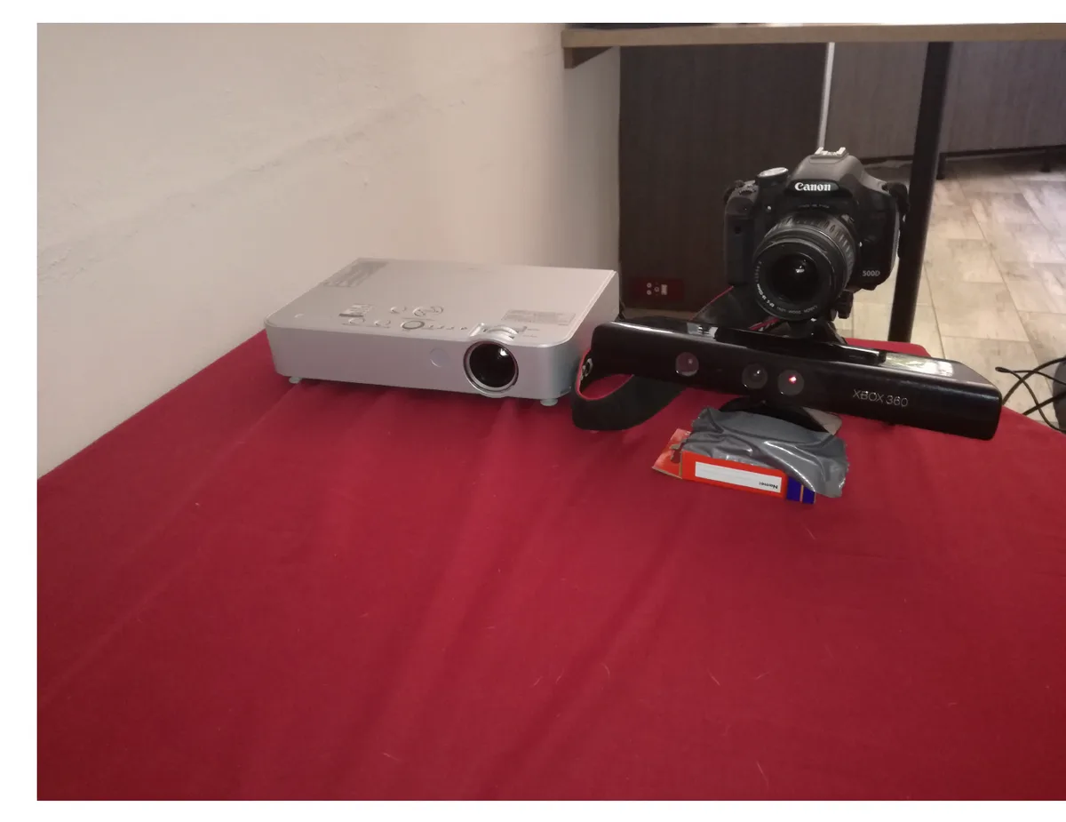
Report Fig. 2 (left), p.7: projector, DSLR and Kinect sharing one stand.
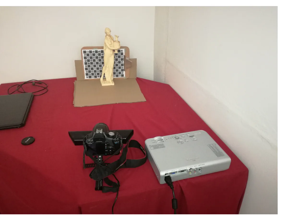
Report Fig. 2 (right), p.7: the scan side, a statue in front of a ChArUco board, the camera and projector’s own housings visible at the bottom.
None of the placement is arbitrary. The projector goes perpendicular to the scanning area, and the report is specific about why: it “gets exposed to approximately the same amount of the projector’s pixels” on both sides of the scene. That word choice matters: the projector’s 1024×768 is the scarce resource here, not the DSLR’s 5184×3456, so the setup optimises for spreading those pixels evenly rather than the camera’s. The image size is kept “just big enough for the objects to be scanned,” because every projector pixel wasted lighting empty table is one fewer pixel of column/row resolution on the actual object. Focus is set so the middle of the scan volume is sharp: the wall behind, out of that plane, is allowed to blur, and it does; more on that below.
The camera sits roughly 25 cm to the left of the projector. That offset is the whole reconstruction budget: no baseline, no triangle, no depth (this was the geometry from post 40, camera ray and projector ray meeting at an angle only large enough to measure if the two viewpoints actually differ). Too little baseline and small depth changes barely move the correspondence; too much and more of the scene falls into one device’s shadow but not the other’s. 25 cm against a scan volume maybe half a metre deep is the report’s compromise, arrived at by “angled and zoomed to ensure the entire scene is in view” rather than a formula.
Getting both devices to agree on the centre
Both the projector and camera need to be centred on the same point in the scene, and there’s no direct way to check that a lens and a projector’s optical axis actually coincide, you can’t see where a projector is “pointing” the way you can sight down a camera. The report’s fix (§4.1) is to project a crosshair and watch it while zooming: “ensuring that as the camera zooms in and out, the cross does not get displaced in the image of the camera.” If the projector and camera aren’t centred on the same 3-D point, zooming moves the apparent position of the cross, a parallax effect, the same reason a foreground object seems to slide against the background when you move your head. If the cross holds still through a zoom, the two are looking at the same point at every distance along that ray, which is exactly the alignment the rig needs.
The actual crosshair is CaptureImages/DrawCorsshairs.py, four lines of NumPy slicing on a
1024×768 black frame:
img[768//2, 1024//2-20:1024//2+20] = 255
img[768//2+1, 1024//2-20:1024//2+20] = 255
img[768//2-20:768//2+20, 1024//2] = 255
img[768//2-20:768//2+20, 1024//2+1] = 255

img[768//2, 1024//2-20+150:1024//2+20-150] = 255
img[768//2+1, 1024//2-20+150:1024//2+20-150] = 255
img[768//2-20:768//2+20, 1024//2-150] = 255
img[768//2-20:768//2+20, 1024//2-151] = 255
(lines 7–15). The first four lines draw the obvious part: a centred cross, arms 40 px long, drawn two rows/columns thick so it survives being resized. The last four are a second, smaller mark offset 150 px to help judge scale as well as centring. Except only one of those four lines does anything.
Driving the DSLR
The Canon 500D doesn’t have a browser-friendly API; it has a shutter and a USB cable. The bridge is
gPhoto2, shelled out to from Python rather than driven through any binding
(CaptureImages/CaptureImage.py, lines 4–20):
GPHOTO_PATH = "gphoto2"
TEMP_GPHOTO_DIR = "capture/out.temp"
GPHOTO_PARAMS = " --capture-image-and-download --filename "

def TakeImage():
    if os.path.isfile(TEMP_GPHOTO_DIR):
        os.remove(TEMP_GPHOTO_DIR)
    os.system(GPHOTO_PATH+GPHOTO_PARAMS+TEMP_GPHOTO_DIR)
    img = cv2.imread(TEMP_GPHOTO_DIR)
    os.remove(TEMP_GPHOTO_DIR)
    return img
os.system is doing all the work: gphoto2 --capture-image-and-download --filename <path> is a
synchronous round trip: fire the shutter, wait for the camera to write the file, wait for it to
come back over USB, then read it into OpenCV. SaveImage two lines later is the same call with a
real destination path instead of a scratch file. The capture loop
(CaptureImages/CaptureCode.py) wraps this in a generator handshake with the projector window:
for every frame GrayCodesWindow’s iterator yields, save one photo, and on the "w" (fully lit)
frame, also fire the Kinect. Folders auto-increment (c_0, c_1, …) by scanning
../captures/<name>/ for the highest existing suffix, so re-running a capture never overwrites an
earlier one by accident.
What a capture bundle actually is
Forty-two files, in one directory: b, w, then h0…h9, ih0…ih9, v0…v9, iv0…iv9
for a 10-bit (1024-wide) projector, exactly the frame order the previous
post derived from GrayImage.getIterator(). b and w are not
optional extras. The decoder two posts from now needs a per-pixel measurement of how bright “fully
lit” and “fully unlit” are at that pixel, because ambient light, projector backlight leak, and
how reflective the surface is all vary across the frame: a fixed global brightness threshold
can’t tell a dim corner of a white object from a bright corner of a grey one. b and w are how
every other frame gets calibrated against the object’s own local dynamic range, and Report §5.1
lists exactly this as the point of the first evaluation experiment: capture the sequence and check
“both the camera and the projector are in focus” and “the structured light images are projected
without distortion” before trusting anything downstream.
Two devices, no channel between them
The real rig’s synchronisation is trivial in a way the browser can’t reproduce: one Python process
drives both the projector window and the shutter, so it always knows exactly which frame is on
screen when it presses the button. A laptop and a phone, each running this page independently, share
no such process: there’s no postMessage, no same-origin frame, nothing. Bluetooth or WebRTC could
bridge that, but both need pairing or a signalling server this static site doesn’t have, which
would turn “open a web page on two devices” into “install something first.” So the sync channel has
to be light itself, the same medium the whole scan already runs on.
Every frame the projector shows gets a small marker baked into its corner: two reference
squares (one forced solid black, one forced solid white) followed by one square per bit of the
frame’s index, lit or unlit. The camera samples all of them, but it never compares against a fixed
brightness. It reads its own black and white squares first, and thresholds every data square
against the midpoint between those two, exactly the same move the real decoder makes with the b
and w frames (Eq. 4.4’s ), just one level up: instead of calibrating “is
this pixel lit,” it’s calibrating “is this marker square on,” using a reference pair captured in
the same shot under the same room light and exposure. A phone’s auto-exposure hunting between
frames, a dim room, a bright one, none of it matters, because the threshold is relative to what
the camera itself just saw, not to an assumed brightness.
That marker is genuinely the only thing making auto-capture possible with zero coordination between the two devices, and it’s also the part I’d flag as fragile rather than solved. The strip has to be visible in the camera’s frame at all, which means composing the shot so a corner of the laptop screen and the actual scan area share the frame, not something a phone held for a real 3-D scan naturally does. And a shaky hand or an angled screen can catch the marker mid-transition, which is why the widget below waits for a handful of consecutive matching reads before it trusts one and fires the shutter, rather than acting on the first read that decodes cleanly.
Try it: the two-device rig
With JavaScript on, this becomes two panes: a projector pane that goes full screen and steps through the Gray-code sequence with a sync marker baked into the corner of every frame, and a camera pane that reads that marker to auto-capture a matching bundle, with a live histogram, a clipping warning, and a bundled synthetic sample so the next post works even with no camera at all.
Open the Projector pane’s full-screen mode on one device (a laptop is the obvious choice, since the pattern needs real screen area) and the Camera pane on another (a phone works, or the same laptop’s own webcam pointed at its own screen as a degraded single-device test: the baseline is close to zero, so the geometry is close to useless, but the capture mechanics all work exactly the same). The projector opens on a focus screen first (the crosshair from above, reimplemented), then the sequence, paged with the arrow keys or a tap on either half of the screen, auto-advancing on a dwell timer if you turn that on. Each pattern frame carries the sync marker in its bottom-left corner.
On the camera side, drag the marker box in the live preview over that corner (or use the X/Y/Size sliders, the drag is a convenience, not the only way in), and turn on auto-capture: green means the marker just read cleanly, red means it didn’t (out of the box’s alignment, too little contrast, or mid-transition), and a captured frame ticks off in the checklist below. The histogram under the preview reads the whole visible frame, not just the marker, and flags it directly when the pattern currently expected is a white frame and more than about one pixel in eight in the preview is already fully saturated: “your white frame is blown out” is a real, specific, actionable warning here, not a guess. A manual Capture next frame button sidesteps the marker entirely, for a dark room where it can’t be read reliably, or for stepping through by hand while watching the other device directly.
Download bundle (.zip) produces the same b.png, w.png, h0.png…iv9.png plus meta.json
layout the previous post’s widget already writes: it’s the same shared pattern engine underneath,
buildFrames/paintFrame promoted out of that widget into src/widgets/_shared/graycode/ for
exactly this: two widgets in this series generating an identical file layout by construction,
rather than by two authors independently agreeing on a naming scheme.
The shared pattern module
src/widgets/_shared/graycode/ is four functions and two tiny types, lifted unchanged out of the
previous post’s widget: buildFrames(numBits, mode, axes, inverses) returns the frame list in
GrayImage.getIterator()’s exact order; paintFrame(frame, w, h, numBits, mode) rasterises one of
them; zipStore(entries) is the hand-rolled stored-mode ZIP writer (local file headers, central
directory, CRC-32 table, PNG is already deflated, so storing costs nothing); saveBlob triggers
the download. The previous post’s widget now imports these instead of
defining them, and this widget’s projector pane does too: the sync marker and the crosshair are
composited on top afterwards, in this post’s own code, since neither belongs in a module a
bit-plane explorer also depends on. The module’s README names all three posts that use
it: this one, the previous one, and the decoder two posts from now, which only needs to read
meta.json’s frame order, not generate anything.
What’s next
A capture bundle, real or the sample, is a pile of exposures with no opinion yet about what any of them mean. Deciding, per pixel, whether a given bit plane was lit turns out to be the hardest and best piece of original code in this repo: shadows, glare and an out-of-focus background all have to come out as “uncertain” rather than a confident wrong answer, and that’s the next post.