Blog · Structured light ·
Deciding whether a pixel is lit: the part everyone gets wrong
Thresholding a Gray-code frame at 128 fails on shadows, glare, dark objects and the projector's own backlight. The fix separates direct from global light and lets the classifier answer "I don't know": the rule that makes the scanner work.
- Interactive
- structured-light
- computer-vision
- gray-code
- wasm
Post 40 in this series ended with forty-two photographs and two small functions (Gray code in, a column and a row index out) and one thing quietly assumed away: that a camera can tell, for a given photograph, whether a projector pixel was on. That assumption is the whole difficulty. Everything past this post (the correspondence map, the triangulation, the point cloud) is downstream of getting that one yes/no/don’t-know answer right, forty-two times, at every pixel, on a photograph that has shadows in it, glare in it, a dark object in it, and a projector that never quite goes to zero even in its “black” frame.
The naive answer is a threshold: pixel above 128, lit; below, unlit. It is also the wrong
answer, and this post, and DecodeGrayImages/DecodeGrayImages.cpp (the 185-line file it is
entirely about), is the two ideas that replace it: split the light hitting a pixel into a
part that came straight from the projector and a part that bounced there some other way, and
then apply five rules that are allowed to shrug.
Light is not one thing
Report §4.2.2 states the model plainly:
is what the camera measures. , the direct component, is light that left the projector and hit this pixel with nothing in between: the signal the whole scheme depends on, because it is the only part that actually carries the Gray-code bit. , the global (or indirect) component, is everything else: light bounced off another surface first, light scattered under the skin of a translucent object, room light, and (the report is explicit about this one) “the projectors back-lighting… the light emitted when the projector is projecting a completely black frame.” A pixel in a cast shadow has and : it is genuinely, physically lit, just not by a beam that tells you anything about a column or row index. Threshold that pixel against 128 and you get a coin flip dressed up as data. Separate into its two components first, and the shadow pixel reports . That’s exactly the signal that says this pixel cannot answer the question, so don’t ask it.
Getting and apart with light you already photographed
Nayar et al.’s trick (cited as [7] in the report) is to project a high-frequency pattern: alternating lit and unlit at a spatial frequency fine enough that any surface patch on the object sees roughly the same average illumination regardless of the exact phase. Under that pattern, barely moves between the pattern and its photographic inverse, while flips almost completely: present under one, absent under the other. Track the max and min a pixel reaches over a stack of these high-frequency exposures and the two components fall out of a small linear system (Eq. 4.4):
where : is the pixel’s intensity under a fully-lit reference frame, its intensity under a fully-unlit one. Nayar’s own version of this projects dedicated 9×9 checkerboard patterns, offset by various pixel amounts, purely to generate /, extra exposures that exist for no reason other than feeding this one equation.
I skipped them entirely. My report states it in one sentence, on p.10: “Rather than using this checkerboard pattern, the highest 3 frequency components of the Gray pattern and their inverses… is used.” A structured-light scan already contains a high-frequency pattern: the finest few bit planes of the Gray-code stack I was going to capture anyway, both axes, pattern and inverse. Reuse those as the “checkerboard” and direct/global separation costs zero extra exposures. It’s probably the best engineering decision in the whole project: I already had the input another paper tells you to go photograph separately, I just hadn’t noticed.
The code (DecodeGrayImages.cpp lines 125–138) takes iHigh/iLow (its names for
/) as the max and min over eight values per pixel: the horizontal and
vertical bit planes, pattern and inverse, at bit indices 6 through 9:
uint8_t iHigh = std::max(std::max(std::max(ph[9][px], pih[9][px]), std::max(pv[9][px], piv[9][px])),
	std::max(std::max(ph[8][px], pih[8][px]), std::max(pv[8][px], piv[8][px])));
iHigh = std::max(std::max(std::max(ph[7][px], pih[7][px]), std::max(pv[7][px], piv[7][px])), iHigh);
iHigh = std::max(std::max(std::max(ph[6][px], pih[6][px]), std::max(pv[6][px], piv[6][px])), iHigh);
uint8_t iLow = std::min(std::min(std::min(ph[9][px], pih[9][px]), std::min(pv[9][px], piv[9][px])),
	std::min(std::min(ph[8][px], pih[8][px]), std::min(pv[8][px], piv[8][px])));
iLow = std::min(std::min(std::min(ph[7][px], pih[7][px]), std::min(pv[7][px], piv[7][px])), iLow);
iLow = std::min(std::min(std::min(ph[6][px], pih[6][px]), std::min(pv[6][px], piv[6][px])), iLow);

float b_inv = (float)pw[px] / (pw[px] + pb[px]);

double Ld = (iHigh - iLow) * b_inv;
double Lg = 2.0 * (iHigh - Ld) * b_inv;Five rules, and a rule that says “I don’t know”
Once and are known for a pixel, deciding whether one particular bit plane was lit there is Algorithm 1 (report p.10), attributed to Xu & Aliaga [6]. and are that pixel’s intensity under the pattern and its inverse; (report default 5) absorbs the projector’s own lensing (per §7.1, “the reason that the inverse pattern is used” in the first place), and (default 15) is a reliability floor below which there simply isn’t enough direct light to say anything at all:
procedure GETISLIT(Ld, Lg, L, L', ε = 5, m = 15)
    if Ld < m:
        return UNCERTAIN                      # too dark to trust at all

    if Ld > Lg + ε and L > L' + ε:
        return LIT                            # rule 1
    if Ld > Lg + ε and L + ε < L':
        return NOT LIT                        # rule 2
    if L + ε < Ld and L' > Lg + ε:
        return NOT LIT                        # rule 3
    if L > Lg + ε and L' + ε < Ld:
        return LIT                            # rule 4

    return UNCERTAIN                          # none of the above
That is the whole idea of the post in seven lines: two guesses that only fire when the direct signal is unambiguous ( clear of , and the pattern clear of its inverse), a symmetric fallback pair that compares the raw intensities against / directly when the first pair can’t decide, and, the part that makes the scanner survive contact with a real photograph, a default of uncertain, not a guess, when nothing fires. A shadow gets marked uncertain instead of confidently decoded into a wrong 3D point later. That third answer is the entire point of this post’s title.
DecodeGrayImages.cpp’s actual getIsLit() (lines 20–28), for comparison against the
pseudocode above, this and getGrayCode() (lines 11–18, the cascading-XOR decode from post
40) are the only two functions in the file that aren’t OpenCV plumbing:
bool getIsLit(double Ld, double Lg, uint8_t pVal, uint8_t ipVal, uint8_t &isInvalid, double epsalon=5) {

	if ((Ld > Lg+epsalon) && (pVal > ipVal+epsalon)) { return true; }
	if ((Ld > Lg+epsalon) && (pVal+epsalon < ipVal)) { return false; }
	if ((pVal+epsalon < Ld) && (ipVal > Lg+epsalon)) { return false; }
	if ((pVal > Lg+epsalon) && (ipVal+epsalon < Ld)) { return true; }
	isInvalid = 255;
	return false;
}
The bug that shipped first
DecodeGrayImages/DecodeGrayImages2.cpp is my earlier version of this file: UTF-16LE
encoded, which is itself a small archaeological clue that I edited it once in a different
tool and never touched it again. Diffing it against the corrected version by hand turns up
two real regressions, not one:
No at all. DecodeGrayImages2.cpp’s getIsLit() has no epsilon parameter
and no tolerance in any of its four comparisons: Ld > Lg, pVal > ipVal, bare inequalities
throughout. Every pixel exactly on a decision boundary, which is precisely the pixels near a
stripe edge where the projector’s lensing (the thing exists to absorb) matters
most, gets decided by single-intensity-level noise instead of being asked to clear a margin.
The invalid mask gets decoded instead of the Gray value: for the H axis, before the loop even runs. Right after zeroing the per-pixel invalid flag, the earlier file has:
pInvalidImageH[px] = 0;
pBinImageH[px] = getGrayCode(pInvalidImageH[px]);
for (int i = NUMBER_OF_BITS - 1; i >= 0 &&  pInvalidImageH[px] == 0; i--) {
	if (getIsLit(Ld, Lg, ph[i][px], pih[i][px], pInvalidImageH[px])) { pGrayImageH[px] += valToAdd; }
	valToAdd <<= 1;
}
That getGrayCode(pInvalidImageH[px]) call runs against the just-zeroed invalid flag,
before a single bit has been classified, so pBinImageH[px] is unconditionally
getGrayCode(0) = 0 for every pixel, full stop. The V axis has the same call, but placed
after its bit loop instead, where pInvalidImageV[px] has settled to either 0 or 255,
so it decodes getGrayCode(0) = 0 for a valid pixel or getGrayCode(255) = 170 for an
invalid one, discarding the accumulated pGrayImageV[px] either way. Column indices are
always zero; row indices are one of exactly two constant values. The scanner would have
produced a point cloud collapsed onto a handful of planes and no obvious crash to say why.
My plan for this post named it correctly as “decodes the invalid mask instead of the gray
value,” and having read both files line by line, that’s exactly what it does, in two
different ways on the two axes. The corrected file simply removes both stray lines and adds
the epsalon parameter used above.
Watching it happen: Fig. 11
The report classifies six individual bit planes of the “Cup” scene and renders lit white, unlit black, uncertain red:
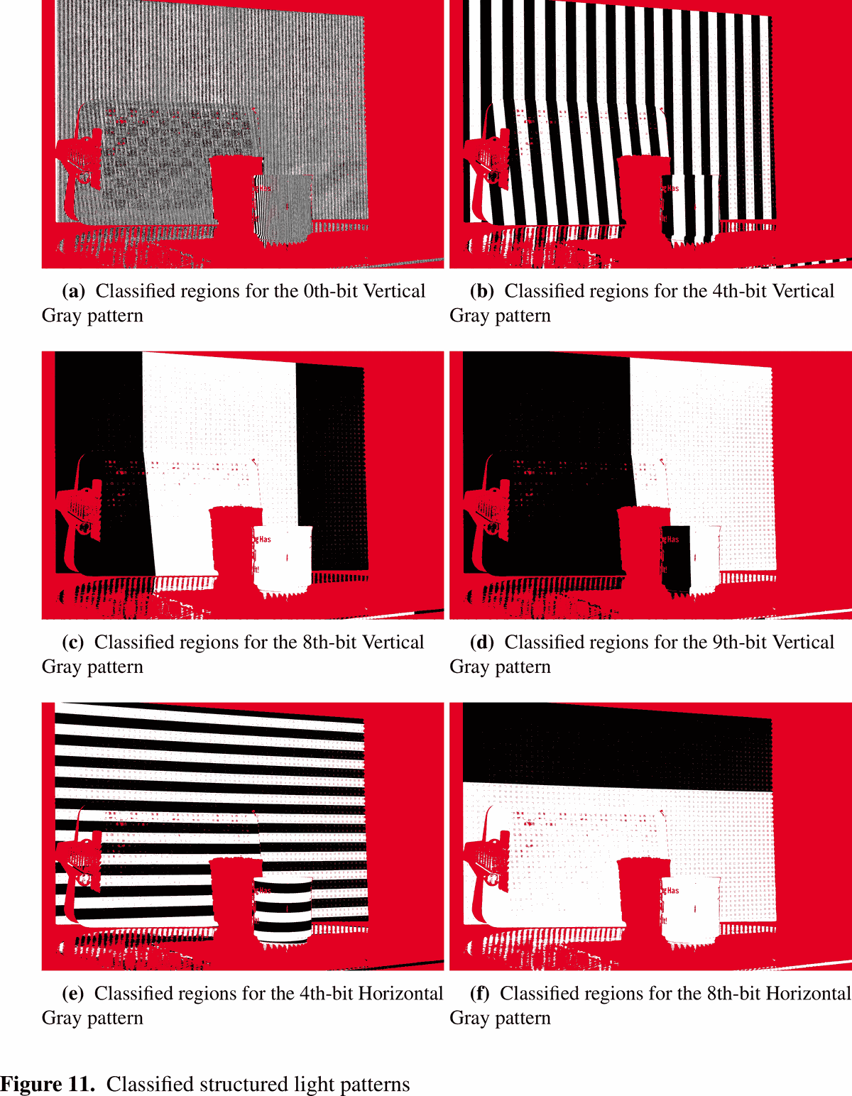
Report Fig. 11, p.20. Everything outside the projector’s throw (table edge, background) reads uncertain by construction: there is no direct light there at all. The fine vertical and horizontal bands in (a) and the freckled texture across every panel are the wall, slightly out of focus (report §7.1: the rig is focused on the scan volume, not the background). Errors concentrate exactly where the report says they would, in the band centres of an out-of-focus region and in the highest-frequency planes.
Close-ups of three specific regions, examined earlier in the report (Fig. 8) before classification and now after it:
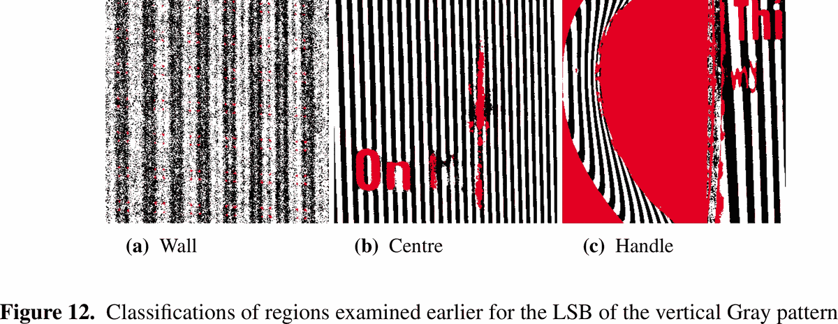
Report Fig. 12, p.21. (a) the out-of-focus wall: correctly-classified bands with speckled uncertain patches at the boundaries. (b) the cup’s centre: clean, with one uncertain column running straight through it: a projector-text watermark bleeding into the pattern. (c) the handle: the glare itself is uncertain, exactly as predicts when a specular highlight saturates the pattern and its inverse almost identically. The report notes a small band around the glare was classified confidently and wrong, which is the interesting failure: not every wrong answer announces itself as uncertain.
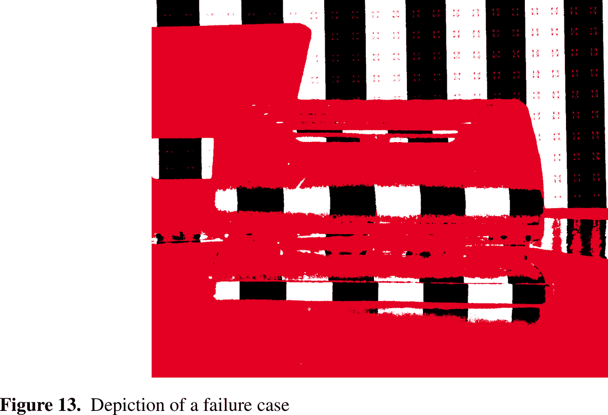
Report Fig. 13, p.21: the “punch” prop, dark-coloured and low-albedo. Almost the entire
object comes back uncertain, not from ambiguity between lit and unlit, but from the
floor. A dark surface reflects so little of the projector’s light that never clears
15, so GETISLIT’s very first check throws the pixel out before the pattern is even
examined. My own diagnosis in the report (§7.2): lowering would recover more of the
object, “however, if this value is lowered, the regions would be classified with minimal
precision”. There genuinely isn’t enough signal there to trust.
Assembling an index, and what “invalid” really means
Once every bit of an axis has an answer, the file reuses getGrayCode() from post 40 (Eq.
4.2’s cascading XOR) to turn the accumulated Gray value into a decimal index, but the loop
that accumulates it has a property worth being explicit about, because it isn’t obvious from
reading the algorithm alone (lines 157–170):
uint16_t valToAdd = 1;
pInvalidImageH[px] = 0;
for (int i = NUMBER_OF_BITS - 1; i >= 0 &&  pInvalidImageH[px] == 0; i--) {
	if (getIsLit(Ld, Lg, ph[i][px], pih[i][px], pInvalidImageH[px])) { pGrayImageH[px] += valToAdd; }
	valToAdd <<= 1;
}
pBinImageH[px] = getGrayCode(pGrayImageH[px]);
The loop walks from the most significant bit (i = 9) down to the least. The moment
getIsLit sets the invalid flag on any bit, the loop guard fails and every lower bit is
simply never examined, left at its default weight of zero. pBinImageH[px] is then computed
unconditionally from whatever partial value was accumulated, invalid or not. A pixel that
went uncertain on its third bit doesn’t get a null index; it gets a real-looking number built
from three good bits and seven implicit zeros, silently indistinguishable from a genuinely
small index unless you also check the invalid mask. Every consumer downstream of this file,
the widget below, and post 52’s triangulator, has to treat the invalid mask as load-bearing,
not optional.
The decoder, live
With JavaScript on, this becomes a live decoder: the recovered direct and global light images, a per-bit classification view reproducing the figure above for any bit and axis, the decoded column and row index maps, and a magnifier that reports one pixel’s raw intensities and which rule of Algorithm 1 fired for each bit, against post 49’s sample scan, or a bundle you drop in yourself.
The widget runs wasm/crates/graycode-wasm, a near line-for-line Rust port of
DecodeGrayImages.cpp, built for exactly this: dozens of u8 image planes in, branchy
per-pixel arithmetic, nothing else. ε and m are live sliders that redecode the entire scan
on every drag. It’s probably the single most instructive interaction in the series: watch
the red uncertain fringe around every stripe boundary breathe as ε moves from 0 (everything
borderline is noise) toward 20 (whole surfaces give up rather than risk a wrong answer).
There’s also a toggle for the high-frequency shortcut itself: switch “use only bits 6–9” off
and the direct/global split is computed from every bit plane instead, including the
low-frequency ones Nayar’s method explicitly avoids. Watch the direct image degrade as
slowly-varying illumination leaks into what’s supposed to be a purely local measurement.
Reading the failure modes back
Report §7.2, in its own words, on what Fig. 11 actually shows once you look past the red: the algorithm “was able to distinguish the shadow of the cup as an ‘uncertain’ region rather than incorrectly classifying the regions”, the headline result, and the reason this post exists. Errors elsewhere sort cleanly into causes: speckle in the out-of-focus wall, concentrated “in the centres of each band” and worst in the highest-frequency planes, which the report notes “isn’t seen in the final point cloud as points further than a certain distance are discarded,” i.e. it doesn’t matter, because nothing that far from the rig survives the crop in post 52 anyway. The glare on the mug’s handle is mostly uncertain, as expected, but “classified a small region… incorrectly,” which becomes a visible mirror-image ghost of the handle sticking toward the camera in the reconstructed cloud: a confident wrong answer downstream of an honest uncertain one upstream. I was candid in the report that the classifier’s honesty doesn’t automatically propagate. Dark surfaces don’t get this kindness at all: the floor is unconditional, and a low-albedo object like Fig. 13’s punch just returns almost nothing.
Five rules, one floor, and a shrug when neither commits: that’s the entire decision procedure this post is about, and it is the reason a photograph of a shadow becomes a gap in a point cloud instead of a bad one.
What post 52 reads
The crate’s output (a column index map, a row index map, an invalid bit mask, and the
direct/global preview images, all width × height, row-major, documented in
wasm/crates/graycode-wasm/README.md) is the exact input post 52’s triangulator consumes:
two per-pixel indices and a bit that says whether to believe them. Everything about how a
3D point gets built from that pair belongs to that post; this one stops at the correspondence.